Best Free Acoustical Measurement Software: Room EQ Wizard (REW) – Audio University
Best Free Acoustical Measurement Software: Room EQ Wizard (REW)
In a previous post, I talked about frequency response specifications and graphs and what frequency response tells us about an audio system. Check out that post to learn what frequency response is and why it’s important.
EASE Software: Enhanced Acoustic Si…
Please enable JavaScript
EASE Software: Enhanced Acoustic Simulator for Engineers
This post answers a slightly different question: How is frequency response measured?
I’ll show you a basic method that you can use to measure the frequency response of your room, your speakers, microphones, or any other audio system!
Mục lục bài viết
How Is Frequency Response Measured?
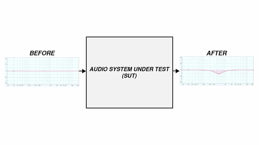
The frequency response of a room, microphone, speaker, or other audio system is measured through a transfer function measurement. This is usually done with a system that compares the output of the system under test with a reference signal to determine the effect (or transfer function) of the device on the test signal.
What Is a Transfer Function?
When we use the method in this post to find the frequency response of a system, we are measuring its transfer function. A transfer function of a system is a mathematical function which models the system’s output for each possible input.
In this case, we will be measuring how an audio system responds to various input frequencies… (Frequency Response)
By sending each frequency equally to the system’s input and measuring the signal again at the output of the system, we should in theory be able to determine the effect that the system has on the signal.
What You Need To Measure Frequency Response
A basic setup for making acoustical measurements consists of:
- Computer
- Measurement Software
- Audio Interface
- Speaker
- Microphone
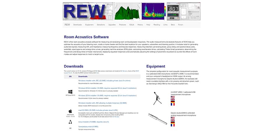
There is no need for a special computer, you can use whatever you have access to. You can even access a free measurement software, called Room EQ Wizard (or REW).
You’ll need an audio interface with at least one microphone input, one line input, and two line outputs.
The speaker you choose will depend on what you’re measuring. If you are measuring the frequency response of a room or a microphone, you’ll want a speaker with a very flat frequency response that can produce all frequencies evenly.
However, you may be measuring the transfer function of the speaker, itself. Or, maybe the transfer function of the speaker and the room combined.
The same goes for a microphone. If you are measuring something other than the microphone itself, you should use a microphone that has as flat a frequency response as possible, or at least a known frequency response that can be adjusted for. Otherwise, the microphone will color the measurement.
Setting Up a Frequency Response Measurement in Room EQ Wizard
To set up a basic measurement, I’ll start by opening Room EQ Wizard. In the top left corner, click “Measure”. This window will pop up:
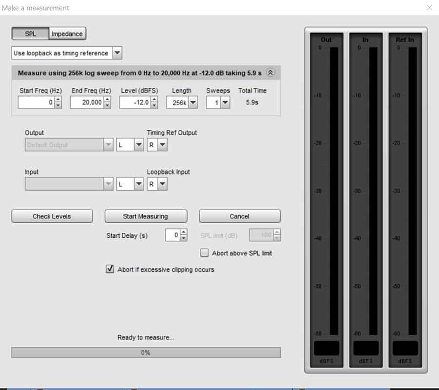
You can see here that the software will test the audio system by sending a frequency sweep signal. This will test how the system responds to each frequency along that sweep.
Let’s set up the inputs and outputs. I want the test signal to play through output 1, or the left output, of my audio interface. That’s the output that I’ll connect to the input of the system I’m testing.
I will connect the output of the system I’m testing to input 1 on my audio interface and select input 1 as the input in the software.
We will also need to set up a path for a reference signal. In a basic test, this is simply a cable that connects output 2 of the audio interface directly to input 2 of the audio interface. This allows the system to adjust for any effect that the interface itself has on the test signal.
The test signal and the reference signal will both be susceptible to the effects caused by the output and input of the interface. I’ll talk about more advanced reference setups later.
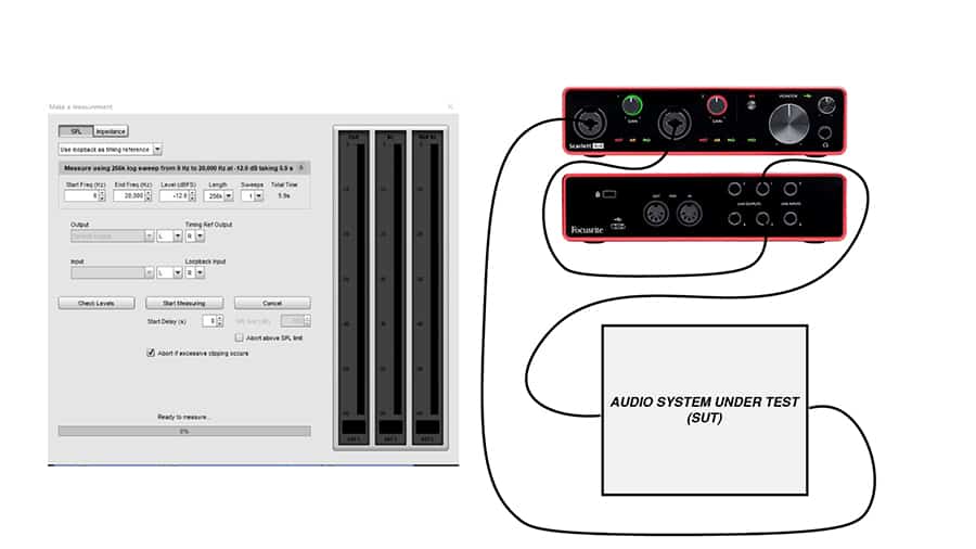
Before testing, it’s important to check levels. The test signal will play out of the two outputs we have selected. The goal is to adjust the gain until the test input signal and the reference input signal are the same level.
Once you’ve got the levels dialed in, click “Start Measuring”. Make sure the room is quiet if you’re making an acoustic measurement.
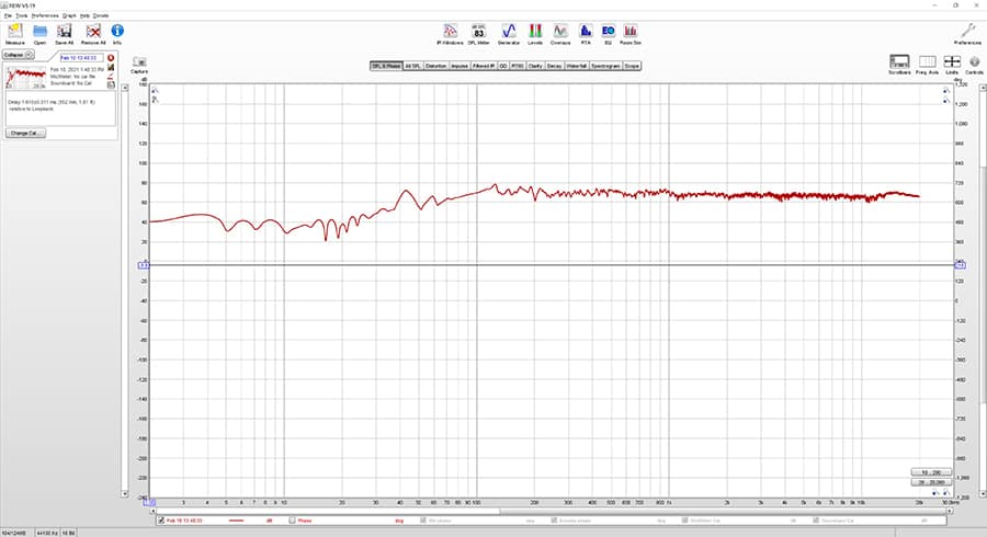
After the test signal plays, you’ll see the results of the test. This graph should look familiar if you have watched my videos on frequency response graphs. To learn how to interpret this graph, check out this post on frequency response graphs and specifications.
Limitations of Frequency Response Measurements
Unfortunately, it’s sometimes difficult to get accurate measurements – especially acoustic measurements. That’s because there are so many variables at play that need to be accounted for.
In a basic measurement of an electronic device, it’s much simpler. Take a look at this diagram:
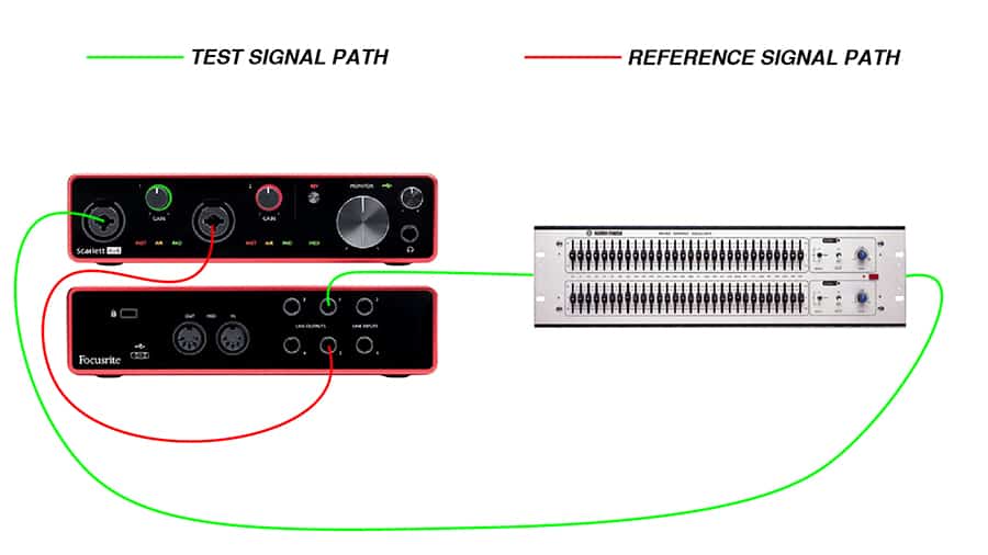
The test signal path includes the interface output, the electronic device (such as an equalizer), and the interface input. The reference signal path only includes the interface output and the interface input. This makes it possible for the software to measure only the changes caused by the electronic device.
However, consider all of the complexities added in an acoustical measurement that didn’t exist in an electrical measurement…
Let’s say I’m trying to measure the frequency response of my speaker. The signal flow would look like this:
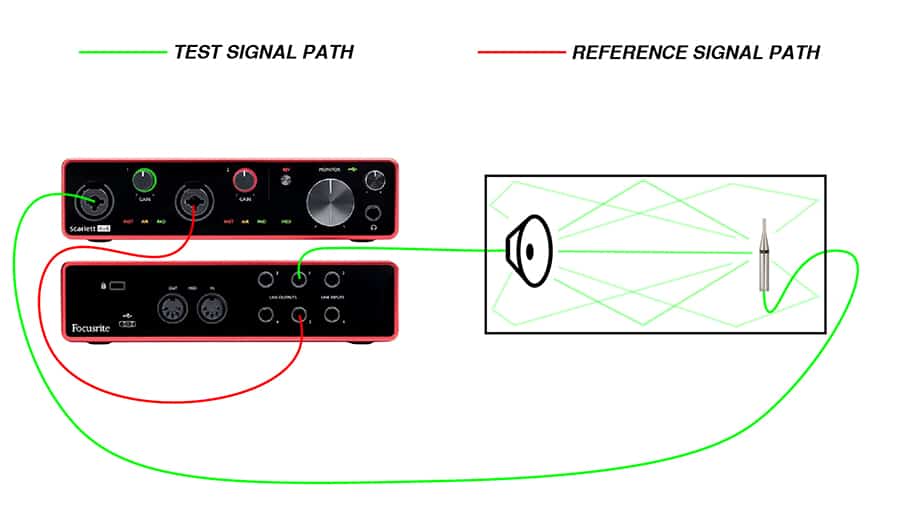
The path of the test signal includes not only the speaker, but the room and the microphone, too.
The acoustic properties of the room could result in cancellations, resonances, and other anomalies that we have no way of accounting for in the reference signal.
The microphone also has a frequency response of its own. If we know the frequency response of the microphone, we can adjust for it. But if we don’t know the frequency response of the mic, it will also affect the results of the test.
Luckily, the great minds in the audio industry have come up with ingenious ways to overcome some of these obstacles.
To mitigate the effects of the acoustic space, many tests of speakers and microphones are done in anechoic chambers – spaces specially designed to eliminate reverberation, resonance, and echo.
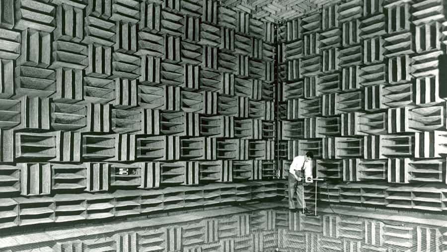 Image Credit: http://www.bell-labs.com/about/history/innovation-stories/anechoic-chamber/
Acousticians, researchers, and system techs also utilize speakers and microphones with a known frequency response so that they can account for the effect the device will have on the transfer function measurements.
Let’s face it… most of us don’t have specially made environments and tools for testing, but that doesn’t mean we shouldn’t experiment and try to create the best measurements possible.
This is a really powerful exercise if you are an audio production student. Try to measure your system at home, or a part of your system.
Do your best to set up a measurement that will help you understand the effect a particular component has on signals passing through your system.
If you don’t have the tools needed to measure a particular component of your system, measure your system as a whole and just remember to consider the effect that each component of the signal path might have on the measurement.


