How to document software architecture? | TSH.io
Every application has an architecture. It might be something simple or something complex. It might be pre-designed or a result of implementation. What’s more, every architecture constantly evolves. That’s why it is important to not only be able to pass everything related to it to the team but also be able to keep that information up to date. So in this article, I focus on how we share such information at The Software House. And generally – how to document your architecture on the daily basis?
Mục lục bài viết
No one standard for documenting software…
When we think about API documentation, the most obvious answer is OpenAPI / Swagger. Sadly, it is not as easy when we talk about architecture.
In reality, there are many standards for a software architecture document. One software architect will use UML for that, another will take a completely different approach. However, there is always one thing in common (of course). Architecture documentation takes more than a single diagram type to be complete in any use case.
Because of that, it is good to have more possible tools we can choose from. That’s why at The Software House we decided to go with a combination of:
-
high-level architecture diagram (
C4
),
-
database schema diagram (
ERD),
-
flowchart diagram,
-
sequence diagram.
Obviously, we rarely use all of them at once – it depends on the architectural system we’re designing – but our minimum is to have a C4 diagram.
What is C4?
C4 is a model that is the closest to be called an architecture documentation standard. It is a set of 3 main and 1 optional diagram:
- context
- container
- component
- code
Each diagram focuses on a specific detail level. The more we get into the details, the more often we need to update that diagram. That’s why for some of them, the key is to generate those instead of creating them manually.
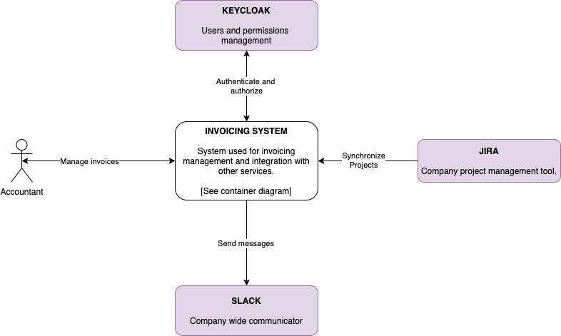
Let’s imagine we’re in the development of an invoicing system for our company. The main users are going to be accountants and we need to integrate it with our internal user management, project management systems, and Slack.
The first diagram we need to create is a Context Diagram.
🏃♂️ Learn how we built an architecture for data-driven systems
- Sports activities and serverless – the architecture for data-driven systems
Context Diagram
It is all about the big picture. We don’t need to know the technical details here. What is important for us are people (actors, who are using the system) and software systems that are part of a business solution.
Context is a diagram that we would show a business person explaining what kind of a system we’re building, what integrations it has, and who is going to use it.
With our invoicing system, it could look like this.
Container Diagram
The second level is a Container Diagram. This time, our focus is on separately running/deployable parts of our system. We could compare it to Docker containers.
Each separate service/database/storage is a separate container on that diagram.
Let’s go back to our Invoicing System. It will have an API, a Frontend, a database, but also a caching layer and file storage. Each of those will be a separate container.
What is important on this level is to describe the technology that is used for that specific container and also how communication between the containers looks like. Is it HTTP? Or maybe is it gRPC? That information needs to be on a diagram.
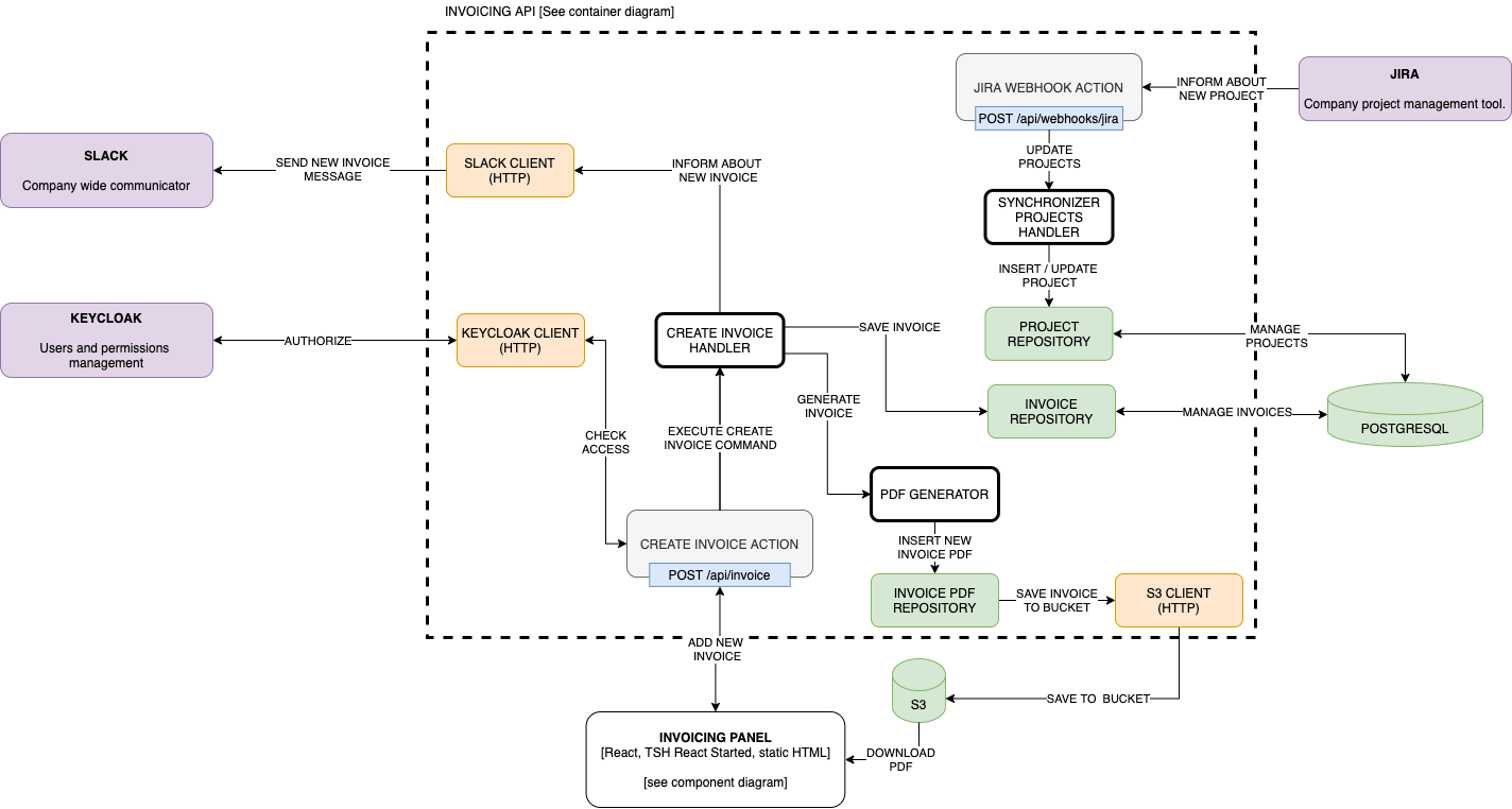
As you can see, we have much more technical information on this diagram. We can see what type of storage we use, what technologies are used for frontend and backend software development, and how those two systems communicate with each other. We can also see all the integrations between specific containers and external services, yet we know nothing about the actual implementation.
This is what the next diagram is about.
🎦 Learn cloud best practices from 2 CTOs
Watch an event that sets expectations vs reality of cloud use.
You’ll learn to choose the right cloud services and when to optimize architecture to maximize results
Hosted by two veterans — our CTO Marek Gajda and Michał Smoliński, CTO of Radpoint, who built cloud-powered products able to service millions of customers
April 12th, at 3:00PM CET
Free to join
See the details
Component Diagram
On this level, we are going to focus on the major building blocks of a specific container. This is where much more implementation details are going to be visible.
Services, repositories, command handlers, external services clients and even endpoints – all of those might be put into this diagram. What is important is to show not only the building blocks but also the communication/relationship between these.
So what would it look like in our Invoicing System? Let’s focus on Invoicing API. The main components are going to be different command handlers, clients to communicate with Keycloak, and Slack. We would also need a few repositories, a PDF management service, and webhook integration for JIRA.
Let’s see that on a diagram.
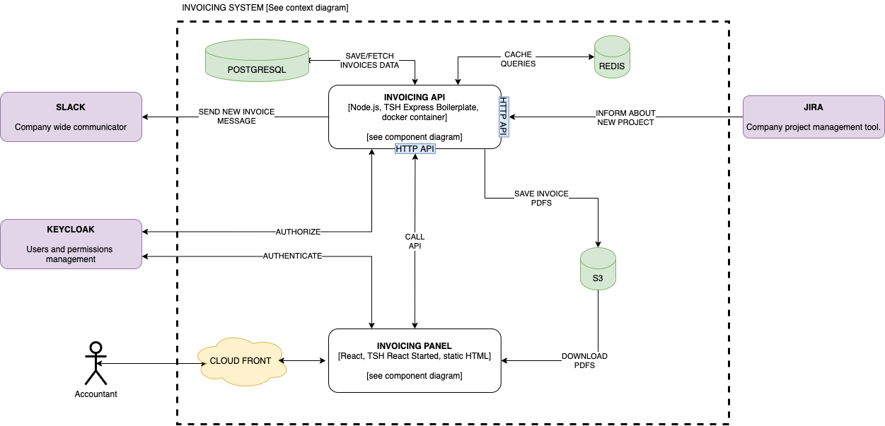
As you can see, a component diagram is not about putting every implementation detail, but focusing on those that are the most important. At The Software House, we also follow a few rules:
- every arrow needs to have a description,
- every name we use needs to be a name that is used in a code (basically when we call something a PDF Generator, there needs to be a thing in the code for that),
- every endpoint/way of communication needs to be visible,
- every color has a meaning (usually we also add a legend for that).
Those simple rules make it easier to follow and design new diagrams since everyone in a company does it in the same way.
Code Diagram
The last diagram that is part of a C4 family is a Code Diagram. This is the one that will be updated the most often, but also is the optional one. At TSH, we don’t really use this diagram. However, the key here is to generate it from the code itself.
It isn’t as hard as it might sound. In reality, we might use some annotations/documentation properties to generate a pretty good UML class diagram that will describe our code and how everything is connected with each other.
A good example of a class diagram could be:
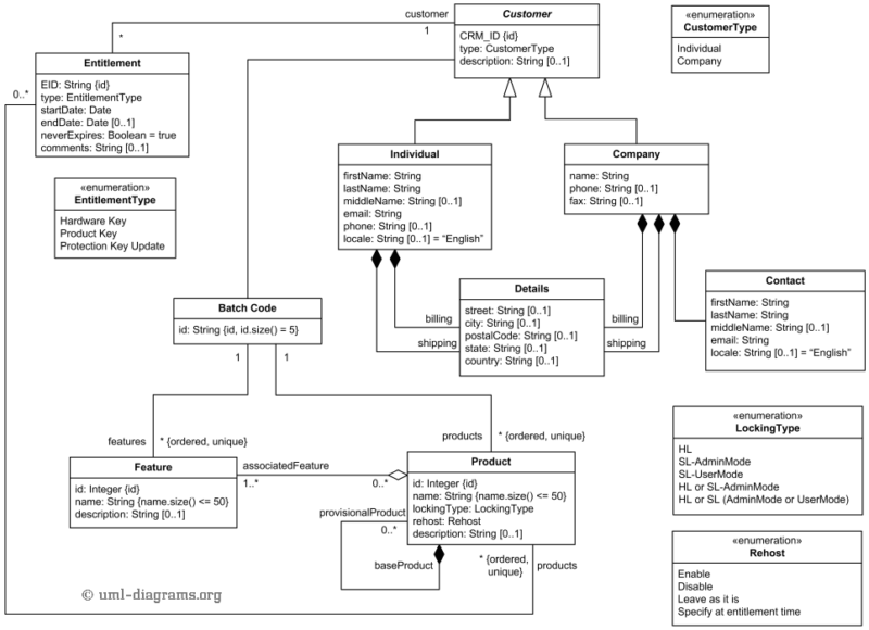
Image source: uml-diagrams.org
It goes so much into the details that with every pull request it will look different, that’s why there is no way to create those manually.
What’s next?
C4 is a relatively simple model to describe your architecture. There is a pretty good benefit of using such an approach – the whole system is easier to understand, making onboarding of new developers faster and easier.
By using C4 everyone can understand the system to the level that is useful for them. Not everyone needs to know about implementation details, however, everyone should be able to understand the high-level goals of a system and what services are used to make it work.
Obviously, C4 is not the answer to everything. In a more complex system, we would need additional types of diagrams – ERD, sequence, flowcharts, etc. However, C4 is an excellent starting point.
Wonder how to document software architectures? This is just one of many questions you need to answer for your next project.
Contact The Software House and tackle them all. The initial consultation is free!
