
Interaction, Collaboration & Sequence Diagrams with Examples
Mục lục bài viết
What is Interaction Diagram?
Interaction Diagram are used in UML to establish communication between objects. It does not manipulate the data associated with the particular communication path. Interaction diagrams mostly focus on message passing and how these messages make up one functionality of a system. Interaction diagrams are designed to display how the objects will realize the particular requirements of a system. The critical component in an interaction diagram is lifeline and messages.
Various UML elements typically own interaction diagrams. The details of interaction can be shown using several notations such as sequence diagram, timing diagram, communication/collaboration diagram. Interaction diagrams capture the dynamic behavior of any system.

 Notation of an Interaction Diagram
Following are the different types of interaction diagrams defined in UML:
- Sequence diagram
- Collaboration diagram
- Timing diagram
The purpose of a sequence diagram in UML is to visualize the sequence of a message flow in the system. The Sequence Diagram in Software Engineering shows the interaction between two lifelines as a time-ordered sequence of events.
The Collaboration Diagram in UML is also called a communication diagram. The purpose of a collaboration diagram is to emphasize structural aspects of a system, i.e., how various lifelines in the system connects.
Timing diagrams focus on the instance at which a message is sent from one object to another object.
Purpose of an Interaction Diagram
Interaction diagrams help you to visualize the interactive behavior of a system. Interaction diagrams are used to represent how one or more objects in the system connect and communicate with each other.
Interaction diagrams focus on the dynamic behavior of a system. An interaction diagram provides us the context of an interaction between one or more lifelines in the system.
In UML, the interaction diagrams are used for the following purposes:
- Interaction diagrams are used to observe the dynamic behavior of a system.
- Interaction diagram visualizes the communication and sequence of message passing in the system.
- Interaction Modelling diagram represents the structural aspects of various objects in the system.
- Interaction diagram represents the ordered sequence of interactions within a system.
- Interaction diagram provides the means of visualizing the real time data via UML.
- UML Interaction Diagrams can be used to explain the architecture of an object-oriented or a distributed system.
Important terminology
An interaction diagram contains lifelines, messages, operators, state invariants and constraints.
Lifeline
A lifeline represents a single participant in an interaction. It describes how an instance of a specific classifier participates in the interaction.
A lifeline represents a role that an instance of the classifier may play in the interaction. Following are various attributes of a lifeline,
- Name
- It is used to refer the lifeline within a specific interaction.
- A name of a lifeline is optional.
- Type
- It is the name of a classifier of which the lifeline represents an instance.
- Selector
- It is a Boolean condition which is used to select a particular instance that satisfies the requirement.
- Selector attribute is also optional.
The notation of lifeline is explained in the notation section.
Messages
A message is a specific type of communication between two lifelines in an interaction. A message involves following activities,
- A call message which is used to call an operation.
- A message to create an instance.
- A message to destroy an instance.
- For sending a signal.
When a lifeline receives a call message, it acts as a request to invoke an operation that has a similar signature as specified in the message. When a lifeline is executing a message, it has a focus of control. As the interaction progresses over time, the focus of control moves between various lifelines. This movement is called a flow of control.
Following are the messages used in a System Interaction Diagram:
Message Name
Meaning
Synchronous message
The sender of a message keeps waiting for the receiver to return control from the message execution.
Asynchronous message
The sender does not wait for a return from the receiver; instead, it continues the execution of a next message.
Return message
The receiver of an earlier message returns the focus of control to the sender.
Object creation
The sender creates an instance of a classifier.
Object destruction
The sender destroys the created instance.
Found message
The sender of the message is outside the scope of interaction.
Lost message
The message never reaches the destination, and it is lost in the interaction.
State invariants and constraints
When an instance or a lifeline receives a message, it can cause it to change the state. A state is a condition or a situation during a lifetime of an object at which it satisfies some constraint, performs some operations, and waits for some event.
In interaction diagram, not all messages cause to change the state of an instance. Some messages do not have the values of some attributes. It has no side effects on the state of an object.
Operator
An operator specifies an operation on how the operands are going to be executed. The operators in UML supports operations on data in the form of branching as well as an iteration. Various operators can be used to ensure the use of iteration and branching in the UML model. The opt and alt operators are used for branching operations. The loop operator is used to ensure the iteration operations in which a condition is executed repeatedly until the satisfying result is produced. Break operator is used inside the loop or iteration operations. It ensures that the loop is terminated whenever a break operator is encountered. If a break condition is not specified, then the loop executes the infinite number of times, which results in crashing the program.
Following are the operators used in an interaction diagram:
Operator
Name
Meaning
Opt
Option
An operand is executed if the condition is true.
e.g., If else
Alt
Alternative
The operand, whose condition is true, is executed.
e.g., switch
Loop
Loop
It is used to loop an instruction for a specified period.
Break
Break
It breaks the loop if a condition is true or false, and the next instruction is executed.
Ref
Reference
It is used to refer to another interaction.
Par
Parallel
All operands are executed in parallel.
Iteration
In an interaction diagram, we can also show iteration using an iteration expression. An iteration expression consists of an iteration specifier and an optional iteration clause. There is no pre-specified syntax for UML iteration.
In iteration to show that messages are being sent in parallel, parallel iteration specifier is used. A parallel iteration specifier is denoted by *//. Iteration in UML is achieved by using the loop operator.
Branching
In an interaction diagram, we can represent branching by adding guard conditions to the messages. Guard conditions are used to check if a message can be sent forward or not. A message is sent forward only when its guard condition is true. A message can have multiple guard conditions, or multiple messages can have the same guard condition. Branching in UML is achieved with the help of alt and opt, operators.
These are some of the most important terminologies used in UML interaction diagram.
Types of Interaction diagram and Notations
Following are the different types of interaction diagrams defined in UML:
- Sequence diagram
- Collaboration diagram
- Timing diagram
The basic notation of interaction is a rectangle with a pentagon in the upper left corner of a rectangular box.
What is a Sequence Diagram?
A Sequence Diagram simply depicts interaction between objects in a sequential order. The purpose of a sequence diagram in UML is to visualize the sequence of a message flow in the system. The sequence diagram shows the interaction between two lifelines as a time-ordered sequence of events.
- A sequence diagram shows an implementation of a scenario in the system. Lifelines in the system take part during the execution of a system.
- In a sequence diagram, a lifeline is represented by a vertical bar.
- A message flow between two or more objects is represented using a vertical dotted line which extends across the bottom of the page.
- In a sequence diagram, different types of messages and operators are used which are described above.
- In a sequence diagram, iteration and branching are also used.

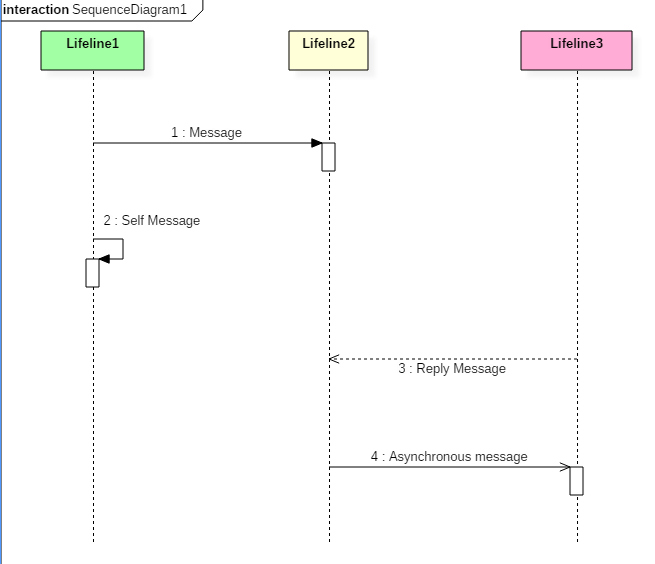
Notations in Sequence Diagram
The above sequence diagram contains lifeline notations and notation of various messages used in a sequence diagram such as a create, reply, asynchronous message, etc.
Sequence diagram example
The following sequence diagram example represents McDonald’s ordering system:

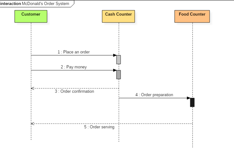 Sequence diagram of Mcdonald’s ordering system
The ordered sequence of events in a given sequence diagram is as follows:
- Place an order.
- Pay money to the cash counter.
- Order Confirmation.
- Order preparation.
- Order serving.
If one changes the order of the operations, then it may result in crashing the program. It can also lead to generating incorrect or buggy results. Each sequence in the above-given sequence diagram is denoted using a different type of message. One cannot use the same type of message to denote all the interactions in the diagram because it creates complications in the system.
You must be careful while selecting the notation of a message for any particular interaction. The notation must match with the particular sequence inside the diagram.
Benefits of a Sequence Diagram
- Sequence diagrams are used to explore any real application or a system.
- Sequence diagrams are used to represent message flow from one object to another object.
- Sequence diagrams are easier to maintain.
- Sequence diagrams are easier to generate.
- Sequence diagrams can be easily updated according to the changes within a system.
- Sequence diagram allows reverse as well as forward engineering.
Drawbacks of a sequence diagram
- Sequence diagrams can become complex when too many lifelines are involved in the system.
- If the order of message sequence is changed, then incorrect results are produced.
- Each sequence needs to be represented using different message notation, which can be a little complex.
- The type of message decides the type of sequence inside the diagram.
What is the Collaboration Diagram?
Collaboration Diagram depicts the relationships and interactions among software objects. They are used to understand the object architecture within a system rather than the flow of a message as in a sequence diagram. They are also known as “Communication Diagrams.”
As per Object-Oriented Programming (OOPs), an object entity has various attributes associated with it. Usually, there are multiple objects present inside an object-oriented system where each object can be associated with any other object inside the system. Collaboration Diagrams are used to explore the architecture of objects inside the system. The message flow between the objects can be represented using a collaboration diagram.
Benefits of Collaboration Diagram
- It is also called as a communication diagram.
- It emphasizes the structural aspects of an interaction diagram – how lifeline connects.
- Its syntax is similar to that of sequence diagram except that lifeline don’t have tails.
- Messages passed over sequencing is indicated by numbering each message hierarchically.
- Compared to the sequence diagram communication diagram is semantically weak.
- Object diagrams are special case of communication diagram.
- It allows you to focus on the elements rather than focusing on the message flow as described in the sequence diagram.
- Sequence diagrams can be easily converted into a collaboration diagram as collaboration diagrams are not very expressive.
- While modeling collaboration diagrams w.r.t sequence diagrams, some information may be lost.

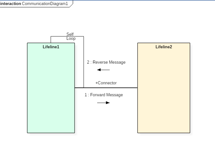
Collaboration Diagram Notations
The above collaboration diagram notation contains lifelines along with connectors, self-loops, forward, and reverse messages used in a collaboration diagram.
Drawbacks of a Collaboration Diagram
- Collaboration diagrams can become complex when too many objects are present within the system.
- It is hard to explore each object inside the system.
- Collaboration diagrams are time consuming.
- The object is destroyed after the termination of a program.
- The state of an object changes momentarily, which makes it difficult to keep track of every single change the occurs within an object of a system.
Collaboration diagram Example
Following diagram represents the sequencing over student management system:

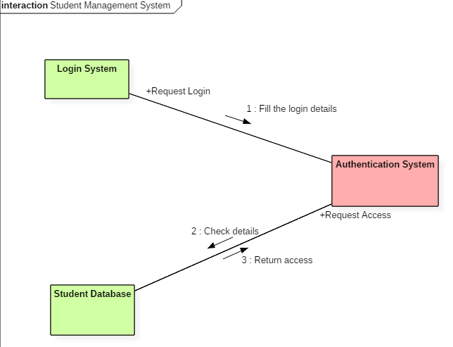
Collaboration diagram for student management system
The above collaboration diagram represents a student information management system. The flow of communication in the above diagram is given by,
- A student requests a login through the login system.
- An authentication mechanism of software checks the request.
- If a student entry exists in the database, then the access is allowed; otherwise, an error is returned.
What is Timing Diagram?
Timing Diagram is a waveform or a graph that is used to describe the state of a lifeline at any instance of time. It is used to denote the transformation of an object from one form into another form. Timing diagram does not contain notations as required in the sequence and collaboration diagram. The flow between the software program at various instances of time is represented using a waveform.
- It is a proper representation of interactions that focuses upon the specific timings of messages sent between various objects.
- Timing diagrams are used to explain the detailed time processing of a particular object.
- Timing diagrams are used to explain how an object changes within its lifetime.
- Timing diagrams are mostly used with distributed and embedded systems.
- In UML, timing diagrams are read from left to right according to the name of a lifeline specified at the left edge.
- Timing diagrams are used to represent various changes that occur within a lifeline from time to time.
- Timing diagrams are used to display a graphical representation of various states of a lifeline per unit time.
- UML provides various notations to simplify the transition state between two lifelines per unit time.
Timing diagram Example
The timing diagram given below represents a few phases of a software development life cycle.

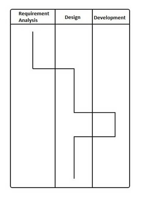
Example of Timing Diagram
In the above diagram, first, the software passes through the requirements phase then the design and later the development phase. The output of the previous phase at that given instance of time is given to the second phase as an input. Thus, the timing diagram can be used to describe SDLC (Software Development Life Cycle) in UML.
Benefits of a Timing Diagram
- Timing diagrams are used to represent the state of an object at a particular instance of time.
- Timing diagram allows reverse as well as forward engineering.
- Timing diagram can be used to keep track of every change inside the system.
Drawbacks of a Timing Diagram
- Timing diagrams are difficult to understand.
- Timing diagrams are difficult to maintain.
How to draw a Interaction diagram?
Interaction diagrams are used to represent the interactive behavior of a system. Interaction diagrams focus on the dynamic behavior of a system. An interaction diagram provides us the context of an interaction between one or more lifelines in the system.
To draw an interaction diagram, you have first to determine the scenario for which you have to draw an interaction diagram. After deciding the situation, identify various lifelines that are going to be involved in the interaction. Categorize all the lifeline elements and explore them to identify possible connections and how the lifelines are related to one another. To draw an interaction diagram, the following things are required:
- The total number of lifelines that are going to be part of an interaction
- is a sequence of message flow within various objects of a system.
- Various operators to ease the functionality of an interaction diagram.
- Various types of messages to display the interaction more clearly and in a precise manner.
- The ordered sequence of messages.
- Organization and a structure of an object.
- Various time constructs of an object.
Use of an interaction diagram
Interaction diagrams consist of a sequence diagram, collaboration diagram, and timing diagrams. Following is the specific purpose of an interaction diagram:
- Sequence diagrams are used to explore any real application or a system.
- Interaction diagrams are used to explore and compare the use of sequence, collaborations, and timing diagrams.
- Interaction diagrams are used to capture the behavior of a system. It displays the dynamic structure of a system.
- Sequence diagrams are used to represent message flow from one object to another object.
- Collaboration diagrams are used to understand the object architecture of a system rather than message flow.
- Interaction diagrams are used to model a system as a time-ordered sequence of events.
- Interaction diagrams are used in reverse as well as forward engineering.
- Interaction diagrams are used to organize the structure of interactive elements.
Summary
- The interactions are simply units of the behavior of a classifier.
- The critical elements in an interaction diagram are lifeline and messages.
- Interaction diagrams mostly focus on message passing.
- Interaction diagrams capture the dynamic behavior of any system.
- Interaction diagram contains sequence diagram, timing diagram, communication/collaboration diagram.
- The sequence UML diagram is to visualize the sequence of a message flow in the system.
- The purpose of a collaboration diagram is to emphasize structural aspects.
- Timing diagrams focus on the instance at which a message is sent from one object to another object.