
UML Timing Diagram – TAE
Timing Diagram
The timing
diagrams are the specialized behavioral modeling diagram. It concentrates on
the various timing constraints. These diagrams can be created when you require learning
how the objects collaborate with each other over a specific time period.
The timing
diagram concentrates on conditions modifying and between the lifelines along
the precarious time axis. These diagrams define the nature of individual
classifiers and classifier’s interactions. It concentrates on the time of event
occurrence producing modifications in the lifeline’s modeled conditions.
Time moves
on the x-axis from the left axis to the right axis, along with distinct
elements of a system that cooperate with each other over the y-axis. These
diagrams illustrate how long every process step takes. We can use these steps
to determine which process steps need time and also to search for areas for
development.
It comprises
of a waveform or graph that portrays the lifeline’s state at a particular time
moment. It represents how various conditions are modified between and inside
the lifelines by the side of a definite time axis. The waveform depicts the
flow between some software plans at numerous time instances.
Mục lục bài viết
Basic Approaches of the Timing Diagram
Some of the
basic approaches of the timing diagram are listed and discussed below:
Lifelines: A lifeline depicts an individual
component within the interaction. It serves as a single entity, which is a
subset of an interaction. It can be displayed by the name of the classifier
that it portrays. The lifelines are positioned inside a diagram frame or a swim
lane.
Condition or State Timeline
These
timelines are continuous. The condition and state timelines are used to
represent the density and temperature where various entities tolerate a
continuous state variation. The timing diagram shows the cooperation of the attributes
and classifier’s state. Also, it shows a few testable conditions, which is a
distinct classifier’s value.
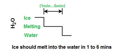
Duration Constraint
A duration
constraint is an interval constraint, which invokes a duration interval. A
duration constraint linguistic is acquired from constraints. It can be used to
identify that a constraint is contended for a span or not. When a negative
trace describes the disrupted constraints, it specifies that the system is
broken down. The graphical association among construct and the duration
interval may illustrate the duration constraint.
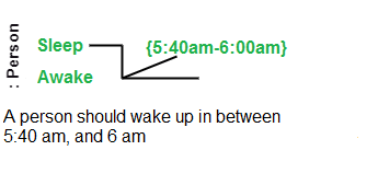
Time Constraint
A timing
constraint is also a constraint of an interval, which invokes towards a time
interval. It can be used to portray that a constraint is a contends or not, as
it is a time expression. The constraints allocate the semantic of time
constraints.
When a
negative trace describes the disrupted constraints, it specifies that the
system is broke down. The graphical
association illustrates a timing diagram among a construct and an interval of
time that it constraints. A tiny line between the occurrence specification and
the time interval may represent the graphical association.
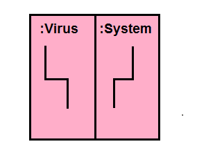
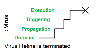
Destruction Occurrence
A destruction
occurrence invokes a message occurrence that illustrates an instance of
destruction is described by the lifeline. It is served at the end of the
timeline by a cross. Afterward, it may destruct the other objects retained by
this object’s composition.
Timing Diagram at a Peek
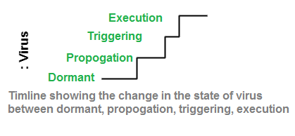
Representation of state Timeline
It
represents the modifications through one state to other states by the change
within in lifeline level. The timeline executes parallel towards that state
when an object is a disposed state. The state change occurs as a change from
one level to other levels vertically. Various cause of the modification can be
the following:
- Time
passage - Condition
inside the system - Message
receipt - An
event that can cause a change.
Representation of Value Lifeline
It
represents the object state among two lines horizontally, that pass each time
each other the changes of the state.
Example of Timing Diagram
Water Cycle
This example
represents a simplified form of a water cycle. As the timing diagrams
concentrates on how every step takes, but not on a system itself. We could
assume of this like the diagram of distinct phases that the water bead cycles
through. The viewers could surely determine the places for improvement, if it
was a process of manufacturing. The timing diagram is a strong tool for
designing a system as effective and simple as possible.
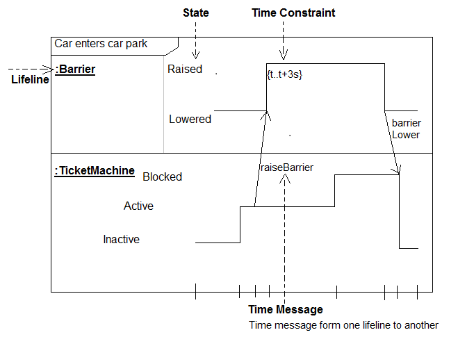
Car Park
The timing
diagram must be persistent with the compatible state diagram and sequence
diagram. For doing this, we can add states to the lifeline for every object
inside the sequence diagram. Then we can obtain the reciprocal timing diagram
much easier. It can be done by checking out the information passing among the
objects opposed to states connected inside the lifeline.
The various
segments of the timing diagram introduce the sequence diagram’s contents. The
following diagram is an example of a car park, which shows a reciprocal timing
diagram.
Advantages of Timing Diagram
- It
keeps track of every change that occurs in the system. - It
can be used to implement forward engineering and reverse engineering. - It
portrays the object state at a specific period of time. - Whenever
the information has been transferred between objects, the timing diagram
focuses on that specific time. - It
describes an object’s processing time in detail. - It
explains the graphical representation of the lifeline state. - These
diagrams contain various notations that can be helpful to clarify a transition
state between two lifelines. - The
timing diagram can be read from left to right, as a lifeline is named on the
edge’s left side. - It
also describes how the object bears modifications in its form over its
lifeline. - It
is occupied with embedded and distributed systems.
Disadvantages of Timing Diagram
- The
timing diagrams are difficult to understand and maintain.